
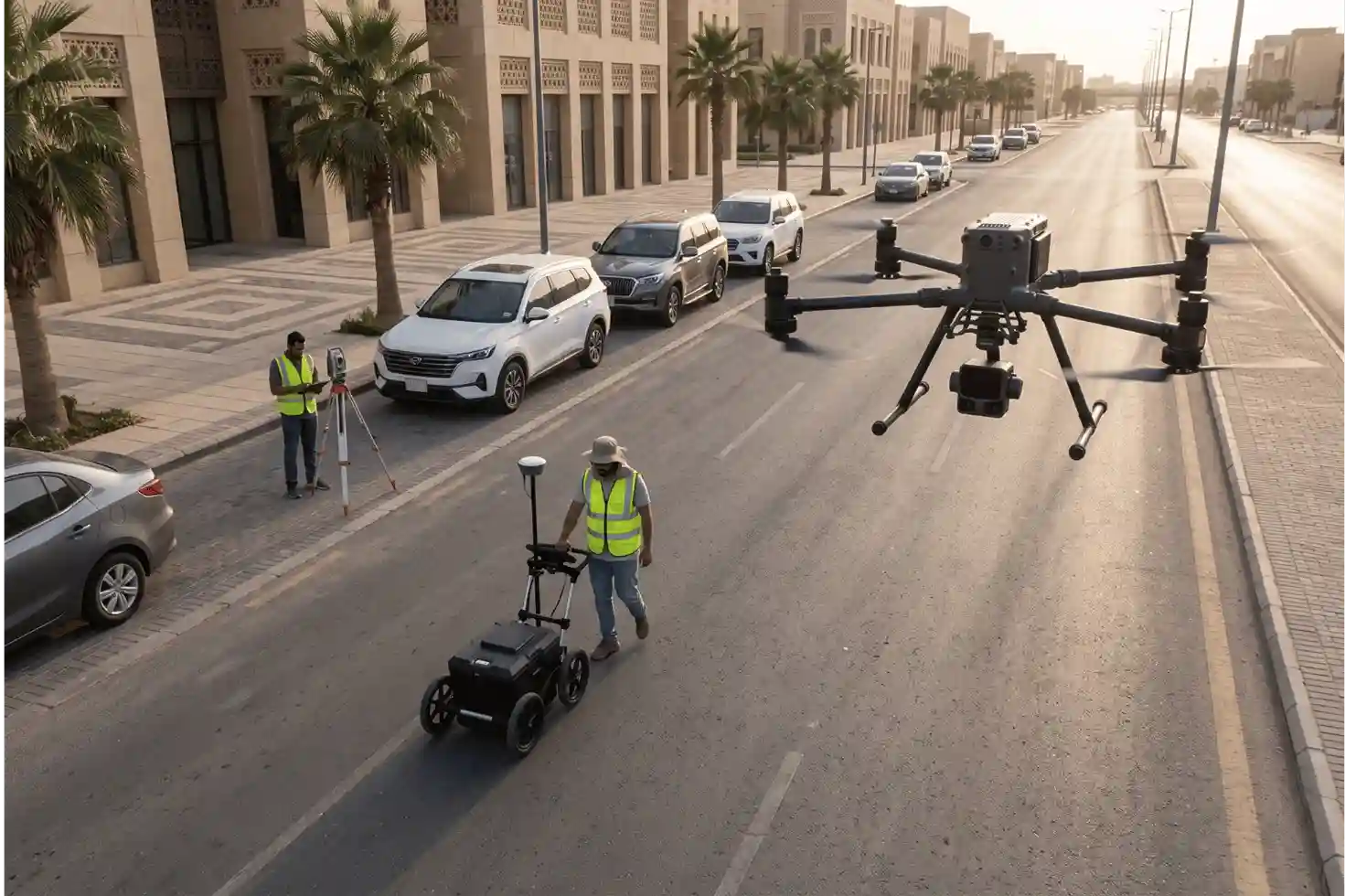
Ground Penetrating Radar (GPR) is one of the most effective non-destructive tools for imaging what lies beneath the surface.
By emitting high-frequency electromagnetic pulses and recording reflected wave amplitudes, GPR detects metallic and non-metallic pipes, electrical duct banks, concrete reinforcement, and subterranean voids without physical excavation.
However, GPR cannot operate as a standalone solution for modern capital project delivery or municipal asset management.
In isolation, a raw GPR survey yields only B-scan radargrams series of parabolic reflections that indicate the two-way travel time and signal intensity of subsurface boundaries.
A standalone radargram does not provide real-world geographic coordinates, does not account for changes in surface topography, cannot evaluate spatial interferences against proposed architectural designs, and cannot manage long-term infrastructure maintenance workflows.
To convert underground geophysical signals into decision-ready spatial intelligence, GPR must be integrated into a broader geospatial and digital engineering workflow. Fusing GPR with Global Navigation Satellite Systems (GNSS), Light Detection and Ranging (LiDAR), Building Information Modelling (BIM), and Geographic Information Systems (GIS) creates an end-to-end framework that connects invisible subsurface assets directly to digital design models and enterprise digital twins.
GNSS and RTK Positioning: Georeferencing Subsurface Findings
A primary limitation of traditional utility locating is the use of localized, temporary ground markings.
Spray-painted lines and surveyor pin flags fade quickly under weather exposure, vehicle traffic, and site excavation, leaving contractors without reliable references when earthwork begins weeks or months later.
Integrating Global Navigation Satellite Systems (GNSS) directly into GPR data collection provides a permanent geographic anchor for every subsurface reflection.
Real-Time Kinematic (RTK) Precision
Standard consumer-grade GNSS units exhibit positional errors of several meters, an uncertainty margin that is unacceptable when working around high-voltage power conduits or high-pressure gas mains.
Subsurface Utility Engineering (SUE) workflows integrate GPR cart systems and handheld locators with Real-Time Kinematic (RTK) GNSS receivers.
RTK positioning relies on a fixed base station or a regional Virtual Reference Station (VRS) Continuous Operating Reference Station (CORS) network.
The base station transmits real-time differential carrier-phase corrections to the rover mounted on the GPR cart. This live synchronization enables field systems to achieve:
- Centimeter Horizontal Accuracy: Restricting horizontal positioning deviations to within 1to2cm across active survey grids.
- Automated Trace Stamping: Tagging each GPR scan line (A-scan) with precise geodetic coordinates (X,Y) as the technician walks or drives the survey path.
- Elimination of Coordinate Drift: Preventing cumulative distance-wheel encoder drift caused by wheel slippage across loose sand, gravel, or wet asphalt.
Standardized Coordinate System Alignment
Mounting RTK rovers onto GPR equipment ensures that all interpreted radar data aligns directly with official national geodetic reference systems, such as UTM projections on the WGS84 ellipsoid or regional datums mandated by survey authorities like the General Authority for Survey and Geospatial Information (GEOSA).
Georeferencing raw survey profiles at the point of capture eliminates the need for manual, post-hoc spatial alignment.
If an unrecorded water pipe or electrical conduit is identified during processing, excavation contractors can navigate back to its physical centerline using an RTK rover, minimizing exploratory excavation and eliminating utility strike risks.
LiDAR and Laser Scanning: Capturing Physical Geometry and Surface Elevations
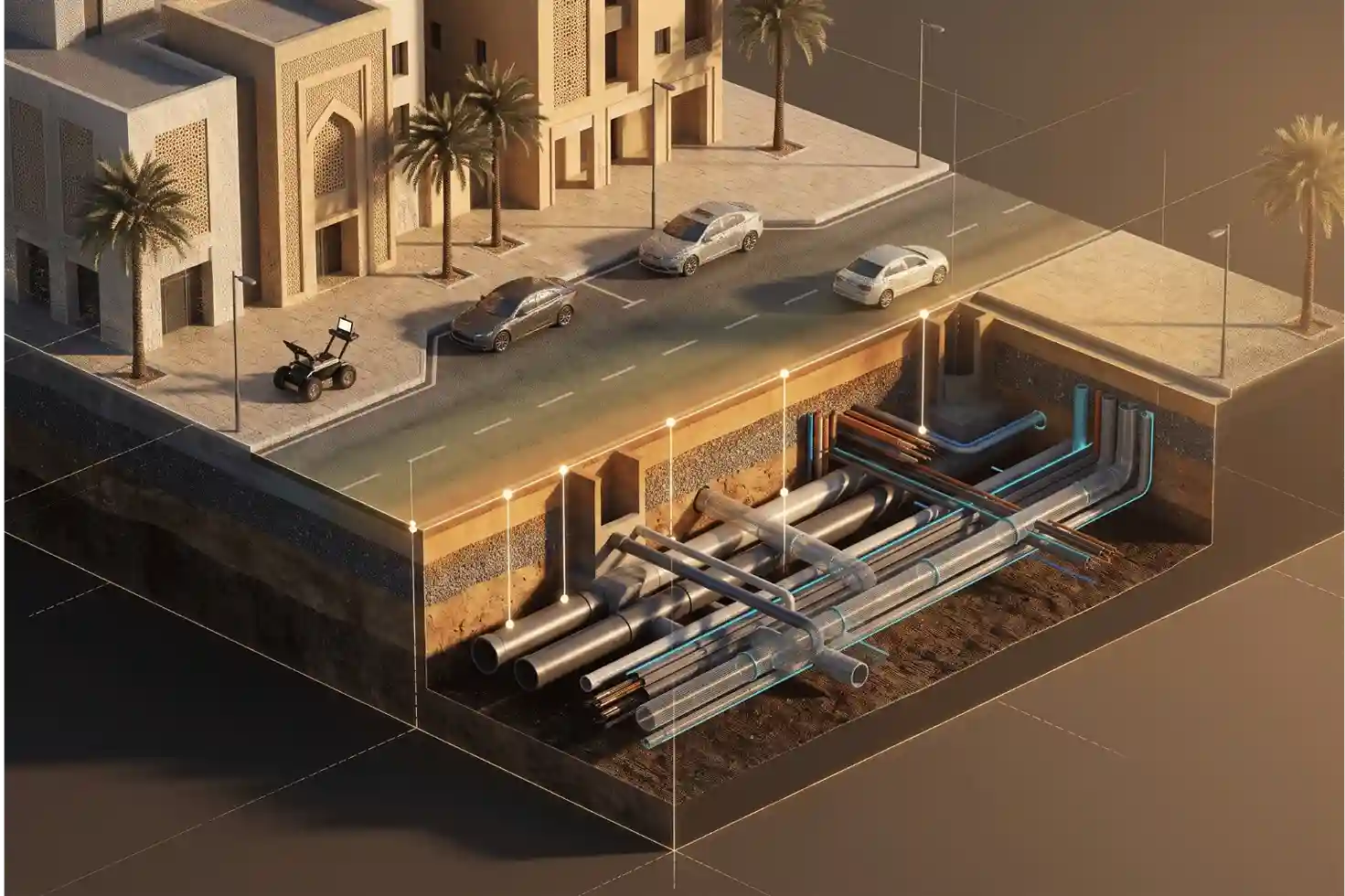
While GNSS provides horizontal positioning (X,Y), it cannot fully capture surrounding physical context or complex architectural geometry.
Ground Penetrating Radar measures target depth (d) as a relative distance beneath the immediate ground or slab surface.
Without high-density surface elevation models, survey teams cannot determine the absolute elevation (Z) of a buried asset.
Light Detection and Ranging (LiDAR) and terrestrial laser scanning bridge this gap by capturing high-resolution surface geometry, providing the vertical reference datum needed to position GPR data in 3D space.
Aerial Drone LiDAR for Corridor Elevation Basemaps
For long linear infrastructure packages, such as water pipelines, district power routes, and arterial highway corridors enterprise multirotor drones (such as the DJI Matrice 400 carrying the زينموز L3 integrated LiDAR and photogrammetry payload) establish the spatial ground plane.
Aerial LiDAR systems emit up to hundreds of thousands of laser pulses per second, penetrating light vegetation and ground canopies to record multiple returns per pulse.
The resulting point cloud generates bare-earth Digital Terrain Models (DTM) with sub-decimeter vertical accuracy.
Underscoring the rapid shift toward aerial survey automation, industry analysis from Fortune Business Insights shows that the global LiDAR drone market reached SAR 992.03 million in 2025 and SAR 1,191.41 million in 2026, and is projected to expand to SAR 5,157.08 million by 2034 at a 20.10% CAGR, as aerial LiDAR surveys replace conventional land surveying to compress multi-kilometer utility corridor mapping timelines by up to 75% while capturing sub-decimeter bare-earth terrain model.
Terrestrial and Mobile SLAM Laser Scanning
In dense downtown streetscapes, industrial process plants, and building interiors where drones cannot operate or where satellite signals are obstructed, mobile Simultaneous Localization and Mapping (SLAM) laser scanners (such as the FJD Trion) provide ground-level reality capture.
Carried by field personnel at walking speeds, mobile SLAM scanners capture millions of points per second to create millimeter-accurate 3D point clouds of:
- Visible Utility Appurtenances: Exact spatial positions and rim elevations of manhole covers, valve boxes, fire hydrants, stormwater inlets, and utility markers.
- Built Envelopes: Curbs, roadway retaining walls, bridge abutments, structural building columns, and finished floor levels.
- Subsurface Tie-Ins: Direct geometric connections where buried pipes and electrical feeders penetrate vertical building foundations or transition into overhead conduit racks.
Registering GPR radargrams within these dense 3D point clouds removes spatial ambiguity.
Technicians evaluate underground radar targets alongside visible surface infrastructure, validating whether a linear reflection aligns with a string of sewer manholes or terminates at an electrical distribution transformer.
BIM and CAD Software: Transforming Radar Profiles into Parametric Models
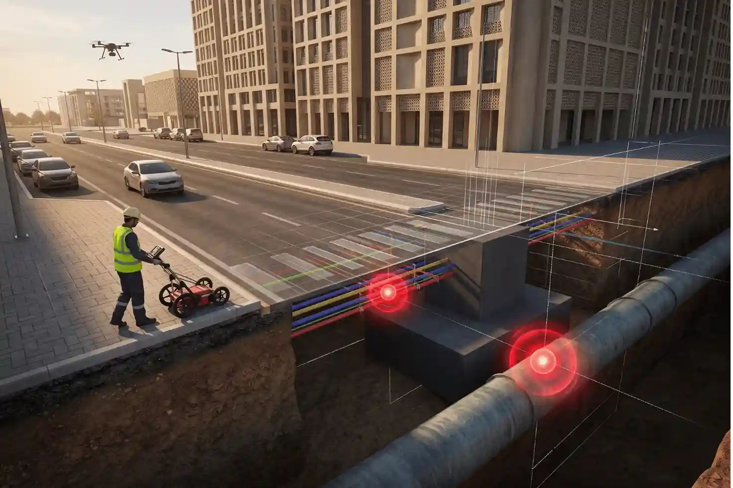
Raw geophysical data cannot be directly coordinated by structural engineers, MEP consultants, or construction planners.
Computer-Aided Design (CAD) and Building Information Modelling (BIM) platforms transform filtered radar reflections into parametric, data-rich 3D digital components.
Civil Infrastructure Modeling in Autodesk Civil 3D
For civil engineering and utility corridor packages, processed GPR vectors import into platforms such as Autodesk Civil 3D.
Using specialized feature-extraction tools (such as Geolitix or GPR-Slice export modules), technicians convert migrated hyperbolic reflection points into continuous 3D pipe and pressure network elements:
- Dynamic Pipe Networks: Converting linear radar traces into cylindrical solids characterized by nominal inner diameter, pipe wall thickness, and outer diameter.
- Profile Views and Hydraulic Slopes: Graphing continuous underground utility lines alongside proposed finished grade profiles, verifying that gravity sewer and stormwater lines maintain mandatory drainage falls.
- Trench Excavation Envelopes: Generating 3D parametric corridor solids to model required mechanical excavation cut volumes, shoring boxes, and aggregate backfill requirements.
Structural BIM and Existing-Condition Modeling in Autodesk Revit
For building refurbishment, structural remediation, and adaptive reuse, high-frequency GPR concrete scanning data connects directly with Autodesk Revit.
Scanning structural slabs, concrete walls, and foundation footings identifies internal rebar spacing, cover depth, post-tensioned cable trajectories, and embedded conduit banks.
Within Revit, structural modellers generate parametric rebar elements and MEP conduits directly inside virtual structural slabs.
This workflow creates an authentic “as-built” BIM model that reflects decades of field modifications, enabling structural engineers to calculate accurate dead/live load capacities and verify shear wall integrity prior to building expansion.
Automated Clash Detection and Risk Elimination
The primary operational benefit of converting GPR detections into BIM objects is pre-construction clash detection inside coordination software such as Autodesk Navisworks.
Multidisciplinary design models, including proposed architectural footings, deep drilled shafts, and stormwater networks are aggregated into a Common Data Environment (CDE).
Automated algorithms scan the consolidated model to identify spatial conflicts:
- Hard Clashes: Physical intersections where a proposed foundation pile intersects an existing high-pressure gas main detected by GPR.
- Soft (Clearance) Clashes: Violations of mandatory separation buffer zones (for example, a new water line designed within 1.0 meter of a high-voltage electrical duct bank).
Highlighting the measurable economic advantages of pre-construction coordination, empirical engineering research published on ResearchGate establishes that integrating pre-construction 3D clash detection and multidisciplinary BIM coordination (using platforms like Autodesk Civil 3D and Revit) eliminates up to 70% of design interferences, decreases on-site rework by 21% to 25%, and reduces overall infrastructure project delivery schedules by 15% to 25%.
| Feature Parameter | Standard GPR Output (Standalone) | GPR Integrated with BIM Software |
| Data Format | 2D radargram profiles / amplitude slices | Parametric 3D solid elements (IFC / DWG) |
| Spatial Reference | Relative depth (d) along survey baseline | Absolute project coordinates (X,Y,Z) |
| Design Utility | Standalone geophysical interpretation report | Automated 3D clash detection in Navisworks |
| Attribute Storage | Basic field notes and radargram headers | Material, nominal size, SUE Quality Level |
| Construction Value | Visual reference for paint-marking crews | Coordinated pre-excavation design models |
GIS Platforms: Enterprise Asset Management and Infrastructure Digital Twins
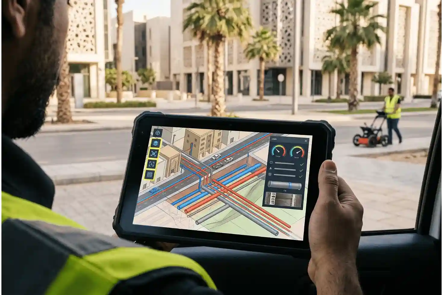
While BIM provides geometric detail for design and construction, Geographic Information Systems (GIS) provide the multi-scale spatial database required for city-wide asset governance.
Enterprise GIS platforms, such as Esri ArcGIS Enterprise and the ArcGIS Utility Network serve as the central integration hub where ground GPR discoveries, aerial drone surveys, and historical municipal records unite into an operational digital twin.
The ArcGIS Utility Network Architecture
Standard GIS layers store utility networks as static, disconnected 2D polylines.
In contrast, the ArcGIS Utility Network models complete physical infrastructure behavior:
- Network Topology and Connectivity: Enforces engineering connectivity rules, modeling how underground pipe segments attach to surface valves, pumps, manholes, and customer service lateral tees.
- Trace Analytics: Enables municipal operators to execute complex network traces. If a buried pipe segment mapped by GPR suffers a catastrophic leak, operators run an isolation trace to identify the exact surface isolation valves that must be closed to shut off pressure while minimizing service disruption to surrounding communities.
- Structural Attachment Modeling: Associates buried utility conduits with physical host structures mapped by surface LiDAR and mobile scanning, such as multi-compartment utility tunnels, duct banks, and bridge attachment brackets.
Multi-Departmental Excavation Permitting and Permitting Dashboards
Centralizing georeferenced GPR datasets within enterprise GIS portals changes municipal excavation permitting:
- Permit Submission: Civil contractors submit proposed excavation boundaries, utility cut routes, or landscaping plans through an online municipal permitting portal.
- Automated Buffer Analysis: GIS spatial analysis engines evaluate the contractor’s polyline against verified GPR and SUE feature layers.
- Quality Level Validation: The system queries the ASCE 38-22 Quality Level of the underlying data. If the area contains unverified Quality Level D (historical paper) or Quality Level C (surface feature) data, the system flags the zone as high risk, mandating Quality Level B (GPR geophysics) or Quality Level A (vacuum excavation) verification before issuing the excavation permit.
- Field Validation via Mobile GIS: Municipal inspectors access the live subsurface digital twin on site using mobile applications (such as ArcGIS Field Maps) paired with RTK receivers, verifying that physical paint markings match the digital utility model before backhoes break ground.
Lifecycle Asset Stewardship and Predictive Maintenance
GPR data integrated into GIS does not remain static after construction. Every buried feature links to a unique enterprise asset identifier (AssetID), synchronizing spatial positions with Computerized Maintenance Management Systems (CMMS) such as SAP or IBM Maximo.
When drainage inspection crawlers audit gravity sewers or municipal teams conduct cathodic protection surveys, condition scores and structural defect logs, such as pipe ovality, joint displacement, or concrete corrosion attach directly to the corresponding GPR polyline in GIS.
Demonstrating the long-term financial and operational value of centralized spatial data, asset management research published on ResearchGate shows that consolidating multi-sensor spatial reality capture, including surface LiDAR, ground laser scans, and subsurface GPR detections into a unified 3D GIS operational digital twin enables predictive asset maintenance frameworks that reduce municipal infrastructure lifecycle repair costs by 35% and extend operating lifespans by up to 25 years compared to reactive maintenance.
Connecting Ground Penetrating Radar with GNSS, LiDAR, BIM, and GIS establishes a unified spatial data loop. GNSS anchors subterranean signals to geodetic coordinates, LiDAR provides the absolute terrain elevation, BIM coordinates underground geometries against planned engineering designs, and GIS maintains the data as an active operational digital twin.
Adopting this multi-tiered reality capture framework replaces outdated drawings with verified field intelligence, eliminating utility strikes, reducing project delays, and safeguarding critical urban infrastructure across its operating lifecycle.

 العربية