
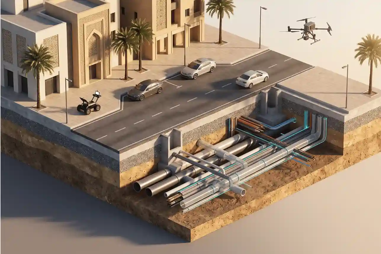
Modern architecture, engineering, and construction (AEC) projects operate in increasingly dense urban environments where physical space above and below the surface is at a premium.
While surface topography, structural framing, and architectural facades are documented using advanced reality capture tools, the space beneath concrete slabs, roadway pavements, and building foundations remains largely invisible.
Ground Penetrating Radar (GPR) provides a non-destructive method for detecting buried utilities, structural reinforcement, and subsurface geological anomalies without disturbing physical assets.
A persistent challenge across capital project delivery and municipal asset management is the reliance on incomplete, fragmented, or outdated as-built documentation.
Subsurface utility drawings and structural engineering records have historically developed in departmental silos, resulting in hand-drawn legacy sketches, conflicting utility schematics, and unrecorded field modifications.
When construction teams begin mechanical trenching, foundation piling, horizontal directional drilling, or structural concrete coring based on inaccurate drawings, they risk damaging critical infrastructure.
The societal and financial consequences of subsurface excavation blind spots are substantial.
Annual infrastructure damage evaluations from the Common Ground Alliance DIRT Report showing that accidental utility line strikes cause an estimated SAR 112.50 billion in annual societal and economic damages across construction corridors, with excavation damage tracking showing persistent line breaks across telecommunication (49%) and natural gas (39%) networks when pre-excavation location verification is absent, illustrate the systemic operational and safety risks of proceeding without verified subsurface data.
The true financial toll of a subsurface strike extends far beyond the direct equipment repair bill.
Civil infrastructure research published on ResearchGate establishing that detailed economic impact studies of underground utility strikes establish an indirect-to-direct cost ratio of 29:1 (and up to 30:1), meaning a direct physical pipe repair bill of SAR 3,750 results in over SAR 108,750 in true project losses through equipment standby, emergency callouts, traffic disruption, and contractor delay claims, confirms how unverified subsurface excavation inflates project budgets.
Preventing these cascading losses requires bridging the gap between subsurface geophysics and digital construction.
Building Information Modelling (BIM) and digital twins provide the collaborative data platforms needed to transform isolated radar signals into structured, georeferenced spatial intelligence.
As public entities and private developers modernize project delivery, market analysis from Fortune Business Insights showing that the global underground utility mapping market reached SAR 5.89 billion in 2025 and SAR 6.56 billion in 2026, and is projected to expand to SAR 15.30 billion by 2034 at an 11.18% CAGR, driven by municipal excavation safety mandates, infrastructure expansion, and integration with 3D digital twins and GIS platforms, underscores the international adoption of digital subsurface asset governance.
Understanding BIM and Digital Twins
What Is Building Information Modelling (BIM)?
Building Information Modelling (BIM) is a structured digital process that generates intelligent, parametric three-dimensional representations of physical facilities and civil infrastructure.
BIM models extend beyond visual geometry; every element within the model acts as a data-rich digital object containing spatial coordinates, material specifications, engineering tolerances, manufacturer details, installation dates, and maintenance requirements.
During design and pre-construction phases, BIM platforms enable multidisciplinary coordination.
Structural, architectural, and mechanical, electrical, and plumbing (MEP) systems are integrated within a Common Data Environment (CDE).
This integration allows automated clash detection routines to identify spatial interferences, such as an air-conditioning duct conflicting with a structural steel beam long before construction begins on site.
What Is a Digital Twin?
A digital twin is a dynamic, virtual replica of a physical asset, process, or system that mirrors its real-world counterpart.
While a standard BIM model often functions as a static baseline representing the asset as designed or handed over at construction completion, an operational digital twin evolves throughout the asset’s active lifecycle.
A digital twin integrates static geometric data (BIM models, 3D meshes, and GIS basemaps) with operational information streams, including Computerized Maintenance Management System (CMMS) tickets, inspection records, drone photogrammetry updates, and real-time Internet of Things (IoT) sensor feeds.
This continuous connection allows municipal authorities, facility directors, and asset managers to monitor asset performance, track material degradation, simulate operational changes, and execute predictive maintenance based on actual physical conditions.
Why Underground Data Matters
Despite the growing adoption of BIM and digital twins, the subsurface environment remains one of the most underrepresented components in modern engineering models.
Most digital twins feature detailed above-ground architecture and mechanical rooms but treat the ground beneath the slab as an empty, uniform mass.
Relying on digital models that lack verified subsurface data introduces critical engineering risks:
- Design Clashes During Excavation: Foundation piles, retention anchors, and drainage trenches designed in BIM can intersect unmapped underground power lines or water mains during site excavation, causing immediate project halts.
- Catastrophic Structural Coring Strikes: During interior renovation, drilling into structural concrete based on inaccurate architectural drawings risks severing high-tension post-tensioned cables, compromising the structural stability of the building.
- Inflated Contractor Contingencies: When tender documentation lacks verified subsurface utility models, bidding contractors add significant financial risk premiums to account for unknown site conditions and potential utility relocation delays.
Rigorous engineering research confirms the economic value of eliminating subsurface blind spots.
Peer-reviewed cost-benefit evaluations published on ResearchGate proving that peer-reviewed cost-benefit analyses of civil infrastructure projects confirm that every SAR 1.00 invested in comprehensive Subsurface Utility Engineering (Quality Levels B and A via GPR, electromagnetic locators, and non-destructive vacuum excavation) returns SAR 4.62 to over SAR 5.00 in verified cost savings by eliminating utility conflict redesigns, contractor delay claims, and unexpected relocations, demonstrate the clear financial return of integrating non-destructive geophysical data into pre-construction planning
How GPR Supports BIM and Digital Twin Development
Underground Utility Mapping
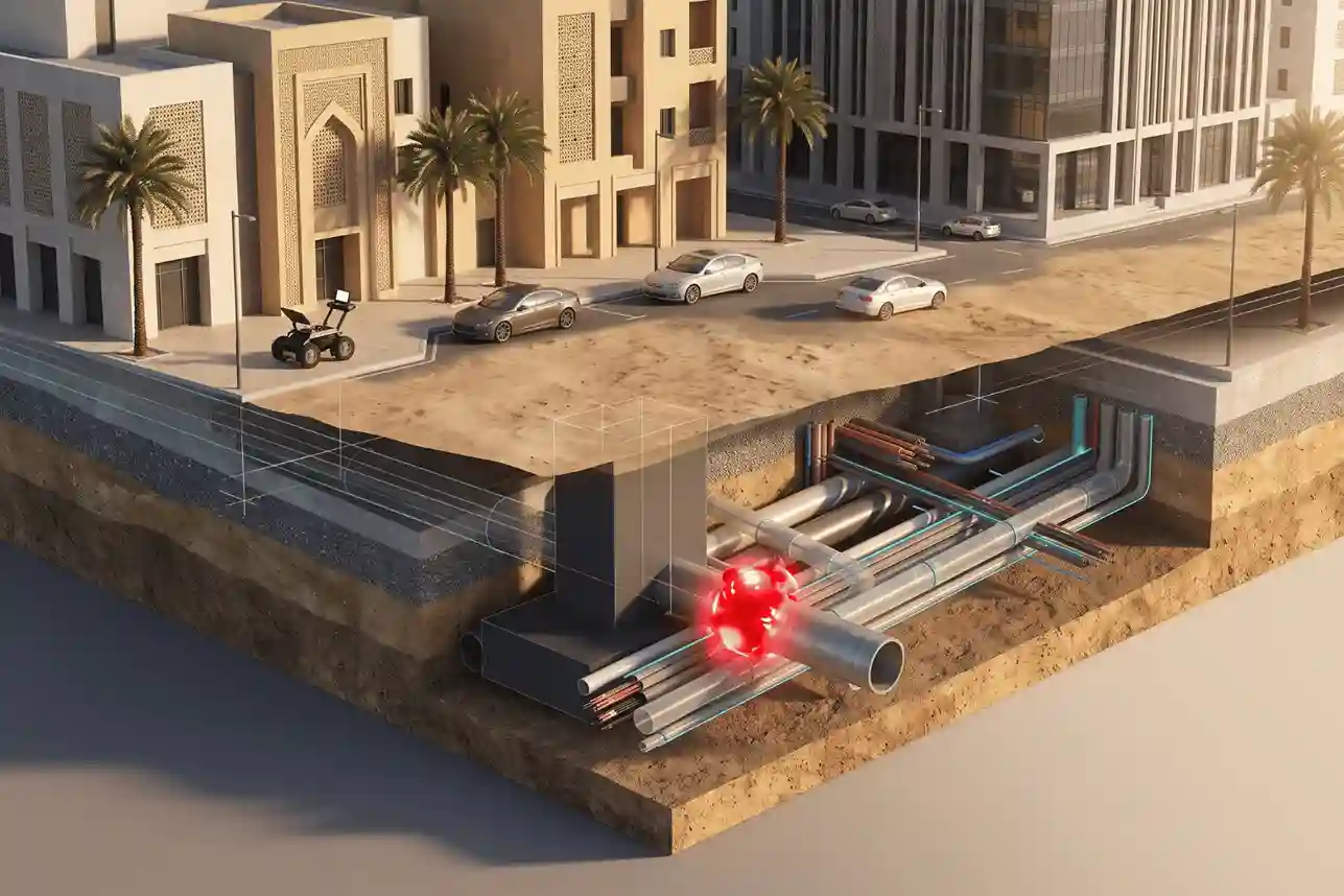
GPR data collection resolves buried utility networks into discrete spatial objects that can be modeled in 3D.
Field geophysicists identify hyperbolic reflection signatures corresponding to pipe crowns and duct banks, extracting depth and horizontal alignment.
By feeding these coordinates into civil infrastructure design packages, engineers convert linear radar traces into parametric 3D pipes with assigned diameters, materials, and elevations.
Integrating these subsurface vectors into BIM clash detection software allows project teams to evaluate proposed utility trenches and building foundations against existing underground assets, resolving design conflicts months before heavy machinery arrives on site.
As-Built BIM for Existing Buildings
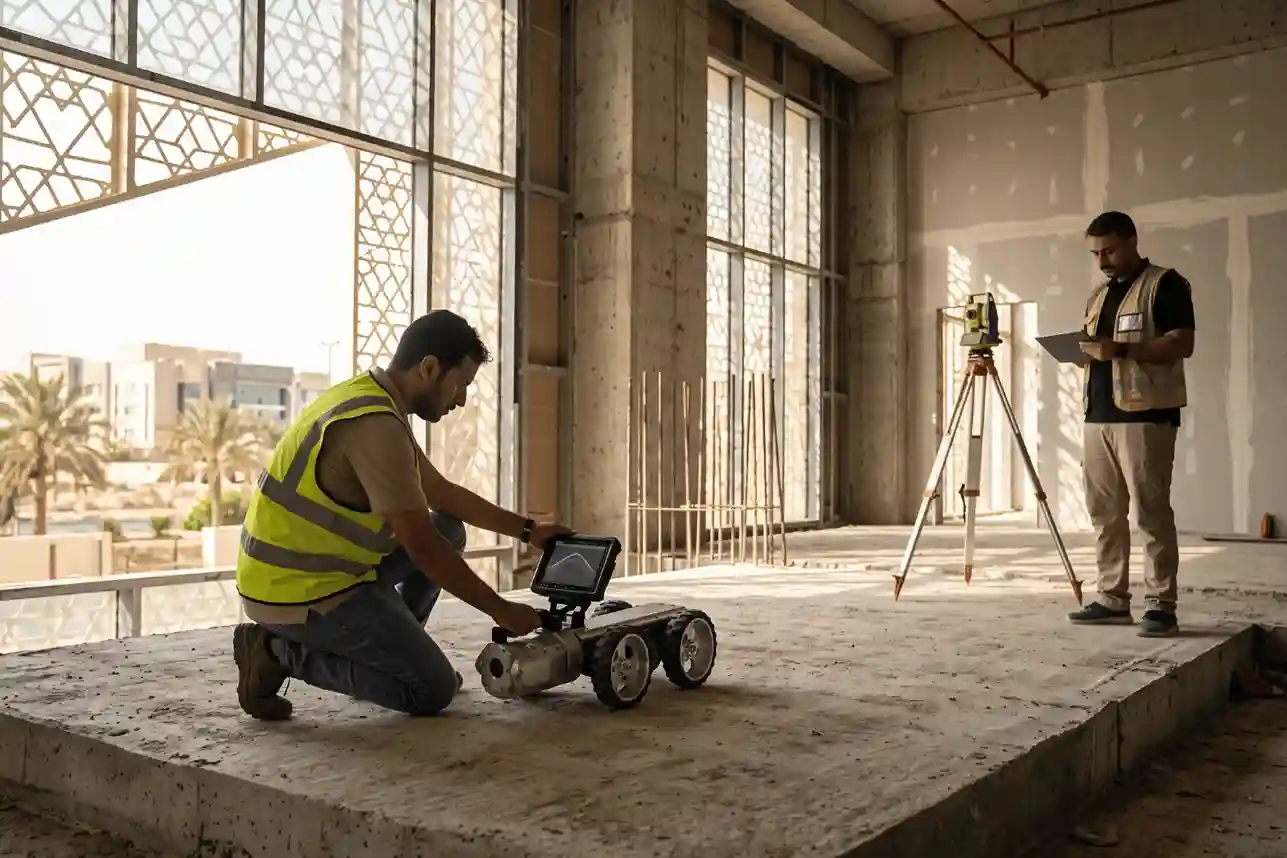
For renovation, retrofitting, and adaptive reuse of aging structures, historical construction drawings are often missing, incomplete, or altered during past tenant improvements.
GPR structural scanning provides the non-destructive insight needed to construct reliable as-built BIM models of existing concrete envelopes.
High-frequency concrete scanning identifies the precise depth, spacing, and orientation of internal reinforcement bars, post-tensioned cable profiles, concrete slab thicknesses, and conduits embedded within floor slabs, beams, and columns.
Translating these scanned geometries into BIM objects enables structural engineers to calculate accurate structural load capacities and model seismic resistance.
Furthermore, MEP contractors can plan new vertical plumbing risers and electrical cores through slabs without the risk of hitting load-bearing structural elements.
Infrastructure Digital Twins

At the municipal, campus, and industrial-city scale, GPR data feeds directly into enterprise GIS platforms (such as Esri ArcGIS Enterprise) and the ArcGIS Utility Network, serving as the subsurface component of large-scale infrastructure digital twins.
To support city-scale modeling, ground-based GPR is paired with aerial drone reality capture to form a unified spatial registry.
Corroborating the efficiency of aerial reality capture, geophysical evaluations published on ResearchGate confirming that deploying UAV-mounted airborne GPR payloads for pipeline rights-of-way and open terrain surveys accelerates subsurface data collection throughput by 10 to 25 times compared to manual pushcart methods, while eliminating 100% of human field pedestrian risks in active traffic corridors and difficult off-road terrain, demonstrate the operational advantages of fusing aerial and subsurface reality capture.
Connecting georeferenced GPR datasets with drone LiDAR elevation models creates a continuous digital twin that extends from aerial space down to subterranean assets beneath roads, public plazas, and utility rights-of-way.
Improving Construction Risk Management
Integrating verified GPR data into BIM and digital twin environments shifts construction risk management from reactive problem-solving to proactive avoidance.
Detailed subsurface models eliminate uncertainty prior to breaking ground, allowing project managers to:
- Verify safe excavation corridors and set precise mechanical digging boundaries.
- Avoid unplanned utility strike disruptions and eliminate costly redesign fees during construction.
- Minimize traffic diversions and public disruption by replacing exploratory open-cut trial pits with targeted non-destructive scans.
- Protect contractor safety and provide reliable documentation for municipal permitting and insurance compliance.
The Workflow: From GPR Survey to a Digital Twin
Step 1: Site Assessment and Survey Planning
The workflow begins by establishing the technical objectives, required level of accuracy, and data boundaries of the survey area:
- Scope Definition: The engineering team determines target deliverables, such as updating an existing architectural BIM model for a building renovation or mapping buried municipal utilities across a 5-kilometer roadway corridor.
- Document Review: Surveyors collect and review available legacy records, including historical CAD files, paper as-built drawings, utility provider schematics, and previous geotechnical boreholes.
- Site Screening: Field teams assess site-specific constraints, noting surface pavement types (asphalt, reinforced concrete, pavers), anticipated soil electrical conductivity, potential electromagnetic interference (EMI) from nearby electrical substations, and site traffic management requirements.
Step 2: GPR Data Collection
Field collection deploys specialized radar hardware matched to the project’s target depths and resolution needs:
- Antenna Selection: High-frequency antennas (1.5 GHz to 2.6 GHz) are selected for concrete slab scanning and shallow embedded services, while dual-frequency carts (200 MHz to 800 MHz) are deployed for street-level utility mapping.
- Scanning Patterns: To generate complete 3D subsurface coverage, field crews collect data along structured orthogonal grids with profile spacing between 0.25 and 0.5 meter across both longitudinal (X) and transverse (Y) directions. For linear utility corridors, longitudinal passes are paired with closely spaced cross-sectional sweeps.
- Georeferencing and Positioning: Every radar scan line is synchronized with real-time positioning instruments. Surveyors use Real-Time Kinematic (RTK) GNSS rovers, robotic total stations, or calibrated distance measurement instruments (encoders) to link radar reflections directly to project coordinate systems.
Step 3: Data Interpretation and Georeferencing
Raw field data files (B-scan profiles) undergo signal processing to isolate target reflections from ambient electronic and soil noise:
- Signal Filtering: Technicians apply time-zero adjustments to correct for antenna elevation, dewow filtering to eliminate low-frequency instrument drift, background removal to clear continuous horizontal noise bands, and time-varying gain (TVG) to amplify attenuated deeper signals.
- Hyperbolic Velocity Analysis and Migration: Technicians analyze hyperbolic curve shapes generated by point reflections to calculate localized wave propagation velocities (v). Migration algorithms reposition reflection energy back to true spatial locations, focusing broad hyperbolas into discrete pipe and rebar cross-sections.
- Absolute Elevation Alignment: Subsurface depths (d) are converted into absolute geodetic elevations by referencing bare-earth Digital Terrain Models (DTM) captured via aerial drone LiDAR.
- Standardized Classification: Data quality is documented using the ASCE 38-22 framework, categorizing lines into Quality Level B (geophysical detection) or Quality Level A (vacuum pothole confirmation).
Step 4: 3D Modelling and BIM Integration
Processed radar features are converted from geophysical interpretation files into solid, parametric 3D elements inside BIM environments:
- Geometric Vectorization: Using specialized bridge tools, technicians convert apex points along migrated radar profiles into continuous 3D polylines and cylindrical solid models.
- Attribute Enrichment: Modeled features are populated with operational metadata attributes, including utility service category, material composition (e.g., ductile iron, PVC, concrete), nominal outer diameter, measured depth, ASCE 38-22 Quality Level, positional confidence tolerances, and field survey timestamps.
- BIM Coordination: The resulting subsurface models import into platforms like Autodesk Revit or Navisworks as native IFC (Industry Foundation Classes) or DWG components, enabling automated clash analysis against planned structural foundations and architectural models.
Step 5: Digital Twin Integration and Updates
In the final phase, the 3D model connects to broader operational platforms to function as an active digital twin:
- Enterprise GIS Ingestion: The 3D subsurface geometries publish into enterprise GIS environments (such as Esri ArcGIS Enterprise) as hosted feature services and 3D scene layers, making the data accessible across municipal departments.
- CMMS Linking: Subsurface assets link to unique enterprise asset identifiers (AssetID), connecting physical components to maintenance tickets, inspection videos from CCTV crawlers, and cathodic protection monitoring databases.
- Continuous Maintenance Protocols: Project governance establishes mandatory protocols requiring contractors to submit verified as-built GPR and drone reality capture data upon completion of any repair, line replacement, or facility expansion, ensuring the digital twin remains accurate throughout the asset’s operating life.
Best Practices for a Successful GPR-to-BIM Workflow
Achieving an accurate, reliable GPR-to-BIM workflow requires adherence to established engineering practices:
- Define Intended Model Use and Detail Early: Project managers must establish the required Level of Detail (LOD) and Level of Information (LOI) before field teams mobilize. A preliminary utility conflict review may only require basic LOD 200 bounding cylinders, whereas complex structural retrofits require LOD 400 detailing showing individual rebar layouts and post-tensioned tendon paths.
- Standardize Survey Accuracy and Coordinates: All field capture—including drone aerial basemaps, ground GPR grids, and terrestrial laser scans—must tie to a single unified project coordinate reference system (such as UTM on the WGS84 datum) using verified survey control points. Discrepancies between local site grids and national geodetic datums cause vertical and horizontal offsets that compromise clash detection.
- Distinguish Interpreted from Verified Features: Digital models must differentiate between geophysically interpreted assets (ASCE 38-22 Quality Level B) and physically exposed assets verified via non-destructive vacuum excavation (Quality Level A). Color-coding or attribute filtering prevents design engineers from assuming unexcavated lines carry millimeter accuracy.
- Preserve Raw Survey Data and Metadata: Retain raw, unmigrated radargrams alongside processed 3D BIM elements. Retaining original data allows future geophysicists to re-evaluate questionable profiles using updated processing algorithms without repeating expensive field mobilization.
- Foster Cross-Disciplinary Collaboration: Successful integration requires continuous communication between geophysicists, land surveyors, BIM managers, structural engineers, and asset owners. Geophysicists must understand BIM modeling tolerances, and BIM modelers must understand the physical propagation limits and depth uncertainties of radar data.
- Enforce Structured Data Governance and Compliance: Subsurface utility networks represent critical infrastructure assets. Ensure data architectures comply with national cybersecurity regulations, such as Saudi Arabia’s National Cybersecurity Authority Essential Cybersecurity Controls (NCA ECC) and SDAIA data privacy guidelines hosting sensitive subsurface spatial models on secure, sovereign enterprise infrastructure.
- Establish Long-Term Model Governance: A digital twin loses value if it is not maintained. Asset owners should embed data update requirements into contractor handover contracts, making the submission of verified GPR and reality capture as-built models a mandatory milestone for final payment certification.
Consult with Our Expert
Bridge the gap between subsurface geophysics and digital construction. Protect your capital projects, eliminate utility strike risks, and build millimeter-accurate BIM models and digital twins with integrated GPR reality capture, drone surveys, and enterprise GIS solutions.
Contact our geospatial specialist to develop reliable digital models for your infrastructure assets.

 العربية