
Executive Summary
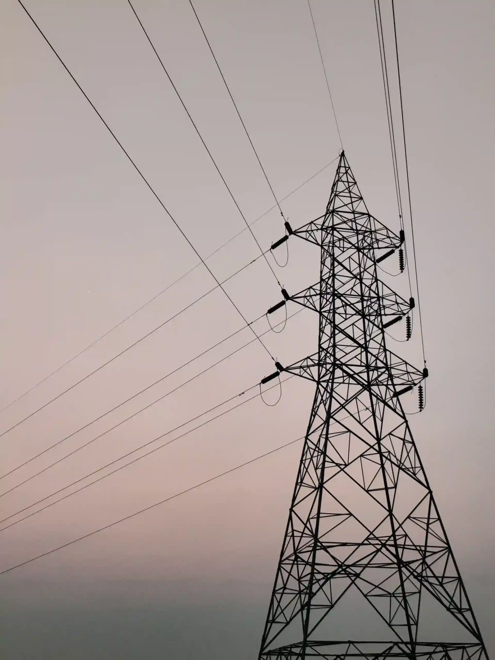
Expanding high-voltage electrical grid infrastructure requires accurate spatial baselines long before heavy construction begins. For a major energy engineering contractor constructing a 132KV double-circuit overhead transmission line (OHTL) and underground cable (UGC) system, mapping an unpaved 185-kilometer linear corridor presented significant terrain and coordination challenges.
Traditional ground surveys over large distances can be slow and prone to elevation errors if control networks are not properly tied to national geodetic datums. To prevent design reworks and contractor billing disputes, a comprehensive topographic and subsurface survey was executed to map all natural and man-made obstacles within a 50-meter Right-of-Way (ROW).
Geospatial Survey Methodology
The survey strategy combined high-accuracy satellite positioning, optical total stations, and ground-penetrating radar across the 185 km alignment.
Static Control Network & RTK Benchmarking
Field survey teams established a permanent geodetic backbone along the entire corridor. Permanent Reference Marks (PRMs) were constructed at regular intervals using long-duration static GPS measurements tied directly to national datum standards and Geoid elevation models. These static stations provided a reliable baseline for deploying Real-Time Kinematic (RTK) GPS receivers to rapidly map ground elevations along a 25$\times$25 meter grid.
Total Station & Subsurface GPR Auditing
Where the proposed transmission corridor crossed existing overhead lines, transport corridors, or major infrastructure, precision Total Station optical instruments measured precise wire heights, structural clearances, and crossing angles. In areas designated for underground cable trenching, Ground Penetrating Radar (GPR) scanned the subsurface to locate buried utility lines before excavation began.
Deliverables & Spatial Data Processing
Field data collected by the GPS and Total Station teams underwent rigorous post-processing and quality assurance checks before conversion into engineering-ready files.
Corridor Geospatial Data Flow:
- Field Data Capture: Static GPS, RTK Grid Mapping & Total Station Angles
- Subsurface Auditing: GPR Scans at Key Trenching Spots
- Post-Processing: WGS 84 / UTM Coordinate Alignment & Elevation Filtering
- Engineering Output: AutoCAD (.DWG) Layers, CSV Point Lists & XYZ Files
The primary deliverables included:
- AutoCAD Control Drawings: Fully layered CAD maps displaying terrain contours, existing roads, water bodies, structural foundations, and rights-of-way.
- Elevation & Topographic Datasets: Georeferenced CSV and XYZ coordinate files providing centimeter-accurate ground elevation profiles for line-sag and tower-spotting calculations.
- Subsurface Feature Logs: GPR anomaly maps marking the location and depth of existing underground infrastructure to protect excavation crews.
Business Impact & Value Delivery
Executing a structured, high-precision corridor survey delivered clear operational and financial benefits to the construction project:
- Eliminated Utility Clashes: Identifying above-ground crossings and underground utilities early prevented costly utility strikes and emergency redesigns during cable trenching.
- Accelerated Civil Works: Delivering georeferenced benchmarks along every 10 km segment gave civil contractors immediate, reliable setup points for tower foundation alignment.
- Verifiable Quantity Audits: Accurate terrain elevation grids allowed project managers to verify earthwork cut-and-fill volumes independently, ensuring fair contractor billing and schedule compliance.

 English