Every decision in a sewer upgrade or drainage expansion depends on the fidelity of the ground surface you hand to designers. In a dense urban corridor next to an international airport, conventional total station and GNSS traverses face line-of-sight gaps and obstruction bias that create uneven accuracy and patchy coverage. That risk is real in North Jeddah, where the area of interest lies adjacent to the airport and spans built-up neighborhoods.
Here is what surface truth looks like at the city scale. We captured a continuous 124 square kilometer topographic dataset in North Jeddah and delivered it as a CAD-ready package in under three months from kickoff. Field acquisition took one month. Processing took two months. This timeline gives engineers a single authoritative surface rather than stitched pockets of data collected over a long period.
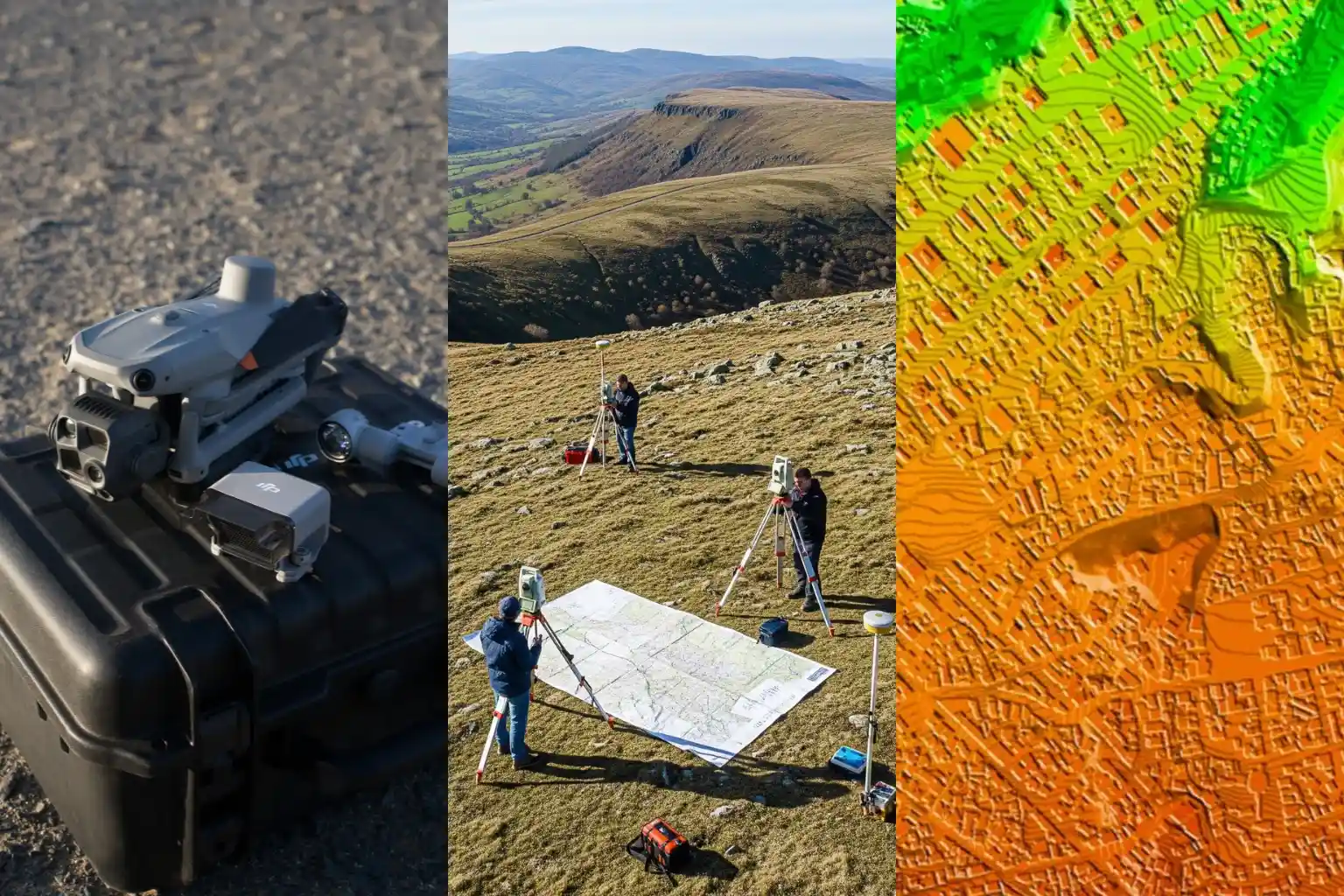
Surface truth is more than a pretty map. It is a defensible stack of products that design teams can trace. The deliverables included an orthomosaic for planimetrics, a Digital Surface Model and Digital Terrain Model for elevation control, contours, 2D CAD drawings, the full list of ground control and independent checkpoints, a documented accuracy assessment, and a formal survey report. These artifacts allow design leads to audit decisions and sign off with confidence.
Accuracy management begins at acquisition. We flew an RTK-enabled drone platform with a full-frame photogrammetry camera and built a high-grade control network. A Trimble R12 receiver established and measured ground control points for adjustment and independent checkpoints for validation. This control strategy reduces reliance on interpolation and tightens both horizontal and vertical residuals across built-up corridors.
The counterfactual underscores the stakes. A traditional approach across this environment would require multiple field teams for about three months and still lean on interpolation between sparse points. The drone-based program concluded the full scope in less than three months while improving accuracy and completeness for downstream CAD and hydraulics. This difference shortens design cycles and cuts rework for utility corridors and drainage upgrades.
Dense Neighborhoods and Airport Constraints
The area of interest covers 124 square kilometers in North Jeddah and sits adjacent to the airport, which makes both data capture and flight planning uniquely complex. Large coverage with airport proximity raises operational constraints, while dense neighborhoods create measurement blind spots for traditional crews.
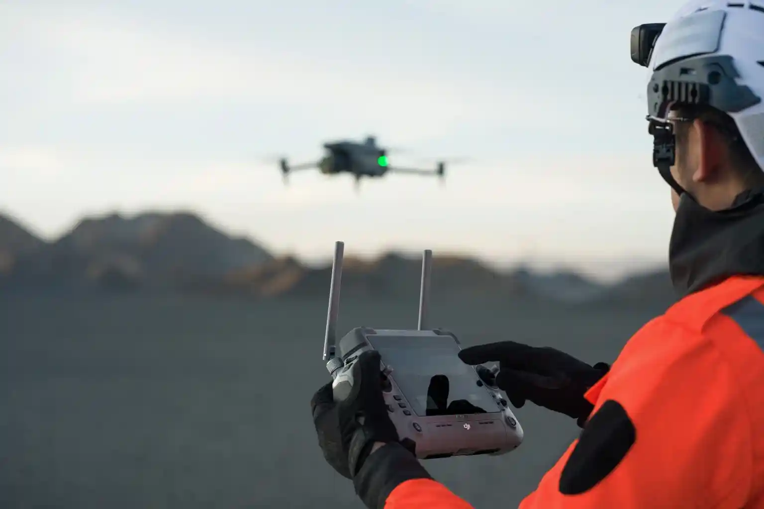
Airport-adjacent realities. In an airport environment, teams must plan flight lines to respect controlled airspace and safety buffers. You manage takeoff and landing zones carefully, maintain strict altitude profiles, and schedule sorties to minimize conflicts with traffic patterns. Geofencing unlocks, NOTAM checks, and close coordination with authorities are standard steps for this kind of work. The goal is predictable, repeatable acquisition without drift in GNSS solutions or interruptions to coverage.
Built-up urban fabric. High building density, narrow corridors, and road canyons reduce line of sight for total stations and can introduce GNSS multipath for traditional rovers. That combination produces coverage gaps and uneven accuracy when you rely on sparse spot levels collected over long traverses. The case conditions explicitly note that built-up areas make conventional topographic surveys “very challenging” and time-consuming.
Why an aerial approach fits this terrain. A drone survey and mapping workflow captures consistent overlap above obstacles and decouples the line of sight from ground constraints. With a DJI M350 RTK and Zenmuse P1 full-frame sensor, you can execute systematic blocks that maintain geometry across long corridors while tying everything to a robust control network. This approach improves continuity through tight streets and variable roof heights.
Time pressure from scale. Because the 124 km² footprint is large and the timeframe is short, a ground-only campaign would require many teams for an extended period, yet still lean on interpolation between sparse points. The case estimates that a traditional approach could take about three months with multiple crews in this exact built-up context. Drone acquisition compresses the field schedule while maintaining fidelity for downstream design.
What this environment demands from the dataset. To serve urban sewer design, the surface must be continuous across roads, intersections, and residential blocks near the airport. That means full orthomosaic coverage for planimetrics and elevation products that remain stable across building shadows and narrow corridors. These conditions are exactly why the project leveraged drone photogrammetry for the topographic survey requirement in this location.
The Method: RTK Photogrammetry Built for Accuracy and Scale
Objective and scope. The brief required a drone-based photogrammetry program to produce a topographic map for a groundwater sewer network design. We planned for city-scale coverage and design-ready outputs that engineers could trust.
Control first. We began with a high-grade GNSS control strategy. A Trimble R12 established the Primary Reference Marker and measured both Ground Control Points for adjustment and Independent Checkpoints for validation. This gives us traceable horizontal and vertical control across built-up corridors where the line of sight is limited.
Airframe and sensor. We executed an acquisition with a DJI M350 RTK paired to a Zenmuse P1 full-frame camera. RTK fixes stabilized camera center positions during flight, which improved the initial network geometry and reduced corrections downstream.
Block design and sortie planning. We divided the 124 square kilometer area into flight blocks that respected airport proximity and dense neighborhoods. We set systematic flight lines to keep overlap consistent through narrow streets and variable roof heights, and we staged takeoff and landing zones to maintain safe operations.
Acquisition window. Field capture finished in one month. This compressed window ensured consistent lighting and seasonal conditions across the entire mosaic, which reduces seams and radiometric variation.
Photogrammetric processing. We ran a rigorous pipeline to turn imagery and control into design-ready surfaces:
- Import imagery and GNSS metadata, then perform initial alignment with RTK positions.
- Constrain the bundle adjustment with GCPs, while holding ICPs blind for an independent accuracy check.
- Generate dense point clouds, then derive the Digital Surface Model and bare earth Digital Terrain Model.
- Create the orthomosaic for planimetrics, followed by contours suitable for design at the requested scale.
- Export CAD-ready drawings and the coordinate lists for all control and checkpoints.
Validation and QA. We computed residuals on checkpoints to quantify horizontal and vertical accuracy and packaged the results as a formal Accuracy Assessment inside the Survey Report. This independent validation gives design teams confidence in alignments, earthworks estimates, and hydraulic modeling that depend on elevation fidelity.
Deliverables and traceability. The handover included the full control and checkpoint lists, orthomosaic, DSM, DTM, contours, 2D CAD drawings, the Accuracy Assessment, and the Survey Report. This stack creates a clear audit trail from raw data to final surfaces.
Why does this method fit this terrain? Built up, airport adjacent environments create line of sight gaps for traditional crews and force heavy interpolation between sparse points. The drone-based program delivered complete coverage in less than three months, end-to-end, and reduced interpolation to achieve more accurate results for design.
The Outcome: Faster, Denser, and More Defensible Data
Speed you can plan around. The program covered 124 square kilometers and hit an end-to-end delivery in under three months. Field acquisition finished in one month, followed by two months of processing. That cadence keeps design schedules moving and prevents rework triggered by stale or piecemeal surfaces.
Density and continuity that cut interpolation. Traditional crews in built-up corridors collect spot levels across long traverses. Obstacles create gaps and force interpolation between sparse points. The drone workflow produced complete, continuous coverage across streets and mixed roof heights, which reduced interpolation and captured the details required for topographic outputs that designers actually use. This directly improves alignment decisions, earthworks, clash checks, and hydraulic modeling.
Accuracy, turnaround, and cost improvements in one motion. The case identifies three measurable benefits: improved accuracy, faster turnaround, and cost reduction. Pairing RTK airborne positions with a robust control network and independent checkpoints delivers traceable accuracy while the aerial scale shortens field time. The net effect is fewer site revisits, fewer redesign cycles, and lower total survey cost for the same or better quality.
Operational reality check. In this airport-adjacent, dense urban setting, a traditional approach was estimated at three months with multiple teams and still faced accuracy challenges from buildings and roads. The drone program concluded in less than three months while meeting the topographic deliverable set. That performance advantage exists specifically because aerial imaging avoids line-of-sight limits and maintains overlap geometry across obstacles.
Why the dataset is defensible. Designers received a complete package: orthomosaic, DSM, DTM, contours, 2D CAD, GCP and ICP coordinate lists, an Accuracy Assessment, and the Survey Report. This stack creates an audit trail from acquisition to final surfaces, so teams can trace decisions and sign off with confidence.
Next Step: Scope Your Corridor with Topographic Certainty
What we need from you to scope accurately
- Area of Interest. Provide the corridor or polygon as a shapefile, GeoJSON, or KML. Include a small buffer so we can plan overlap at the edges.
- Design requirements. Share the target drawing scale, contour interval, and any minimum feature list for planimetrics.
- Accuracy targets. State horizontal and vertical tolerances for acceptance so we align the control and QA plan.
- Coordinate reference. Confirm the map projection and vertical datum for deliverables and control.
- Constraints. Flag airport proximity, restricted zones, and sensitive sites so we integrate permissions and geofencing from day one. This matters in airport-adjacent and built-up areas like the precedent project site.
How do we design the program?
- Control strategy. We specify Primary Reference, Ground Control Points for adjustment, and Independent Checkpoints for blind validation. The precedent used a high-grade GNSS workflow with Trimble R12 for PRM, GCP, and ICP work.
- Acquisition plan. We select an RTK aerial platform with a full-frame mapping camera. The precedent used the DJI M350 RTK with Zenmuse P1 for the mapping sorties. We define altitude, target GSD, and overlap to hold geometry through narrow streets and mixed roof heights
- Block layout and staging. We split the AOI into flight blocks, place TO/LZs outside congestion, and sequence sorties to clear airspace windows. This approach handled a 124 km² urban footprint next to an international airport in the precedent.
- Processing and QA. We align imagery with RTK centers, constrain the bundle with GCPs, keep ICPs blind, then produce orthomosaic, DSM, DTM, contours, and 2D CAD. We publish the Accuracy Assessment and full Survey Report with GCP and ICP coordinate lists for traceability.
What you get, packaged for design
- Design-ready deliverables: list of GCP and ICP coordinates, orthomosaic, DSM, DTM, contours, 2D CAD drawings, Accuracy Assessment, and Survey Report. These are the same classes of outputs delivered in the previous program.
- Schedule expectation: reference performance for a large urban AOI was one month acquisition and two months processing, delivered in under three months end-to-end. Your exact schedule will depend on AOI size, permissions, and contour density.
- Risk controls: airport adjacency and dense neighborhoods are known challenges for traditional surveys. The aerial method avoids line-of-sight gaps and reduces interpolation while keeping timelines predictable.
Your quick start checklist
- Send AOI geometry and design specs today.
- Confirm CRS and vertical datum, plus accuracy tolerances.
- Note airspace and site constraints so we pre-load permissions and geofences.
- Request a sample tile under NDA. We will cut an orthomosaic plus DSM/DTM inset for review.
Call to action
Turn your corridor into a surface your engineers can trust. Share your project inputs, and we will return a scoped proposal with a flight plan, control layout, QA gates, schedule, and a sample tile for review.
Got it. Here are 4 super simple visuals that still land the key points. Each comes with a minimal depiction, a clear title, tight ALT text, a one-line caption, and a short description.