Project Profile
‘
| Parameter | Project Specifications |
| Industrial Sector | Utilities & Energy Public Infrastructure |
| Project Type | Topographic Right-of-Way (ROW) Corridor Survey |
| Corridor Scope | 8.43 kilometers in length / 20 meters in width |
| Measurement Density | 5×5 meter survey grid |
| Field Execution Window | 7 to 10 days total |
Project Summary & Objective
Constructing new high-voltage overhead transmission lines requires absolute spatial precision to safely route power across highly irregular landscapes.
The primary objective of this infrastructure project was to complete a comprehensive topographic survey of a narrow, designated utility corridor running through a rugged terrain profile.
By establishing a highly detailed 3D baseline map, the survey aimed to provide civil engineering teams with the exact spatial data required to plan foundational structures, optimize material layouts, and calculate safe vertical clearance boundaries.
التحديات التقنية
- Rugged Terrain Geometry: The project area spanned 8.43 kilometers of highly uneven, hilly terrain that introduced severe elevation shifts and steep physical slope variances.
- Satellite Signal Obstructions: Winding valley structures and steep rocky ridges created physical boundaries that risked blocking or degrading standard GPS satellite signals during field tracking.
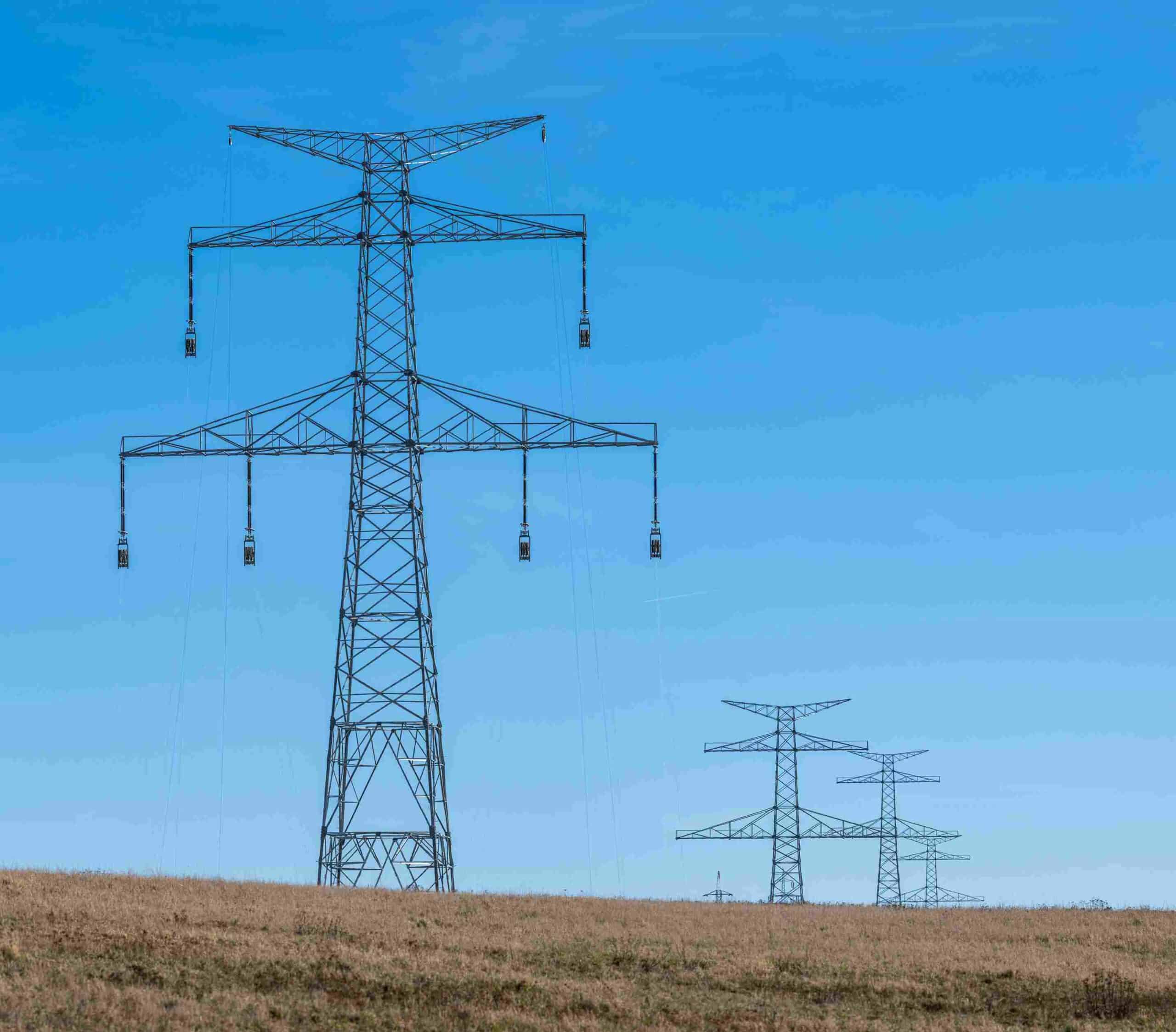
- High-Risk Infrastructure Crossings: The new power corridor was designed to intersect several existing public infrastructure assets, including active overhead lines, lighting poles, telecom towers, pipelines, and railroads.
- Zero-Tolerance Clearances: To prevent catastrophic structural or electrical interference, engineers needed to map the exact 3D coordinate profiles and sagging points of these existing overhead lines to define safe clearance envelopes.
Hybrid Survey Methodology & Execution
To bypass physical terrain limitations and achieve sub-centimeter-level accuracy, the mission deployed an integrated, dual-sensor ground surveying framework:
1. Primary GNSS Grid Mapping
Field crews utilized high-precision Differential GPS units operating via the Real-Time Kinematic (RTK) method to track multiple global satellite constellations, including GPS, GLONASS, Galileo, and BeiDou. This configuration mapped the primary ground topography across a uniform 5×5 meter measurement grid to record general elevation changes.
2. Secondary Total Station Laser Tracking
For areas where steep slopes blocked satellite tracking signals, surveyors deployed electronic Total Stations. These laser-based instruments targeted specific physical structures to capture the exact coordinates and absolute heights of intersecting overhead lines, utility poles, and sag positions.
3. Rigorous Quality Control protocols
A dedicated field team consisting of 5 on-site surveyors, backed by office-based data processing and quality control specialists, cross-verified all redundant sensor data against documented workflows to eliminate potential measurement errors.
Deliverables & Key Outcomes
- Multi-Format Engineering Data: The final geospatial package was delivered in standard coordinate spreadsheets (CSV format) and high-fidelity 3D digital blueprints (CAD format) for direct integration into structural design software.
- Flawless Clearance Profiles: The dual-sensor workflow successfully mapped all physical intersection points, allowing developers to precisely calculate cable clearances and safely position the new transmission network.
- On-Time Project Completion: Despite the difficult terrain and complex layout obstacles, the coordinated 5-man field crew completed all data acquisition and quality reviews smoothly within the projected 7-to-10-day timeline.
Optimize Your Utility Layouts
Never risk infrastructure structural integrity on unverified terrain contours or estimated wire clearances.
Consult with our expert and deploy surveying assets for your upcoming corridor infrastructure project.